engine Ram 1500 2013 Get to Know Guide
[x] Cancel search | Manufacturer: RAM, Model Year: 2013, Model line: 1500, Model: Ram 1500 2013Pages: 196, PDF Size: 9.66 MB
Page 3 of 196

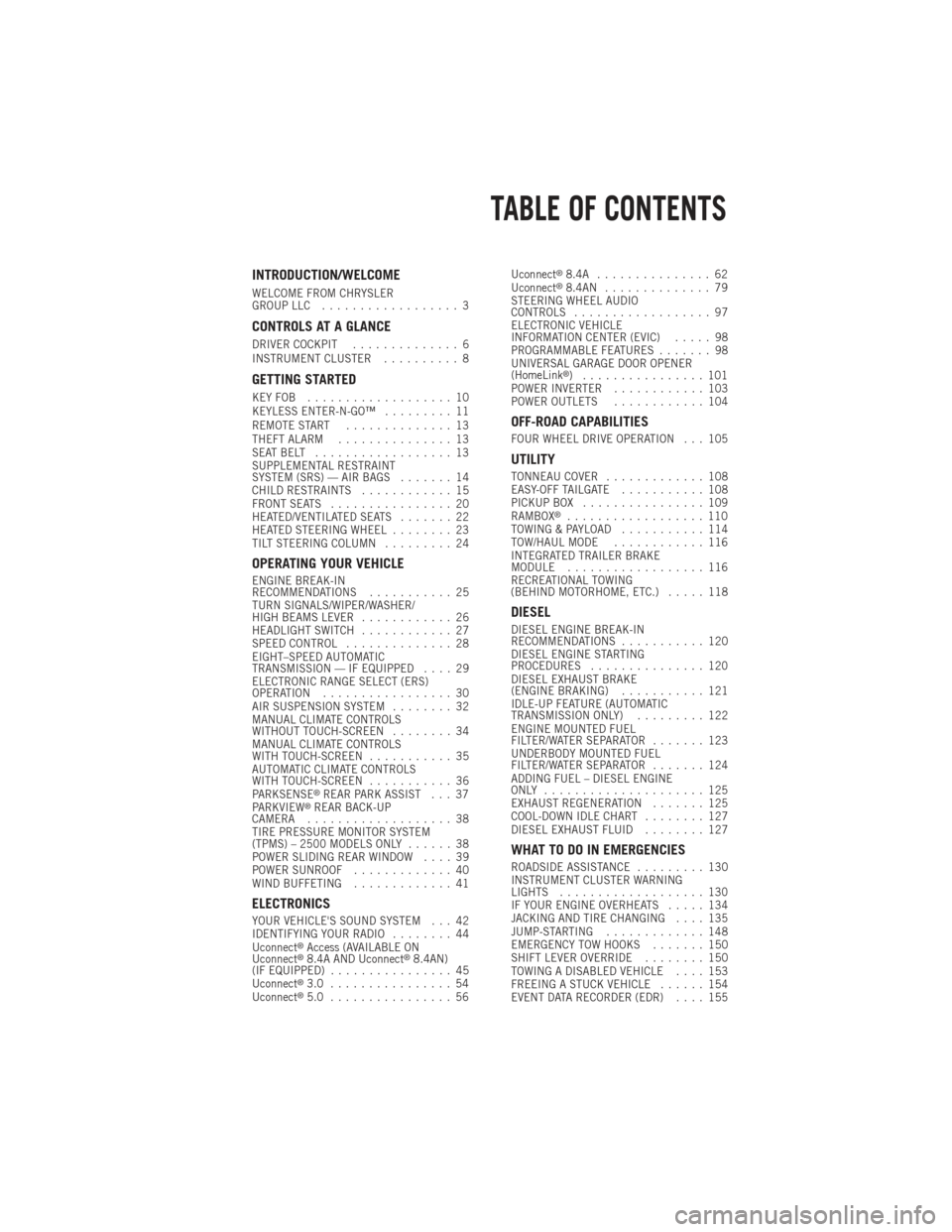
INTRODUCTION/WELCOME
WELCOME FROM CHRYSLER
GROUP LLC.................. 3
CONTROLS AT A GLANCE
DRIVER COCKPIT .............. 6
INSTRUMENT CLUSTER .......... 8
GETTING STARTED
KEYFOB ................... 10
KEYLESS ENTER-N-GO™ ......... 11
REMOTE START .............. 13
THEFT ALARM ............... 13
SEATBELT .................. 13
SUPPLEMENTAL RESTRAINT
SYSTEM (SRS) — AIR BAGS ....... 14
CHILD RESTRAINTS ............ 15
FRONT SEATS ................ 20
HEATED/VENTILATED SEATS ....... 22
HEATED STEERING WHEEL ........ 23
TILT STEERING COLUMN ......... 24
OPERATING YOUR VEHICLE
ENGINE BREAK-IN
RECOMMENDATIONS........... 25
TURN SIGNALS/WIPER/WASHER/
HIGH BEAMS LEVER ............ 26
HEADLIGHT SWITCH ............ 27
SPEED CONTROL .............. 28
EIGHT–SPEED AUTOMATIC
TRANSMISSION — IF EQUIPPED .... 29
ELECTRONIC RANGE SELECT (ERS)
OPERATION ................. 30
AIR SUSPENSION SYSTEM ........ 32
MANUAL CLIMATE CONTROLS
WITHOUT TOUCH-SCREEN ........ 34
MANUAL CLIMATE CONTROLS
WITH TOUCH-SCREEN ........... 35
AUTOMATIC CLIMATE CONTROLS
WITH TOUCH-SCREEN ........... 36
PARKSENSE
®REAR PARK ASSIST . . . 37
PARKVIEW®REAR BACK-UP
CAMERA ................... 38
TIRE PRESSURE MONITOR SYSTEM
(TPMS) – 2500 MODELS ONLY ...... 38
POWER SLIDING REAR WINDOW .... 39
POWER SUNROOF ............. 40
WIND BUFFETING ............. 41
ELECTRONICS
YOUR VEHICLE'S SOUND SYSTEM . . . 42
IDENTIFYING YOUR RADIO ........ 44
Uconnect
®Access (AVAILABLE ON
Uconnect®8.4A AND Uconnect®8.4AN)
(IF EQUIPPED) ................ 45
Uconnect
®3.0 ................ 54
Uconnect®5.0 ................ 56 Uconnect
®8.4A ............... 62
Uconnect®8.4AN .............. 79
STEERING WHEEL AUDIO
CONTROLS .................. 97
ELECTRONIC VEHICLE
INFORMATION CENTER (EVIC) ..... 98
PROGRAMMABLE FEATURES ....... 98
UNIVERSAL GARAGE DOOR OPENER
(HomeLink
®) ................ 101
POWER INVERTER ............ 103
POWER OUTLETS ............ 104
OFF-ROAD CAPABILITIES
FOUR WHEEL DRIVE OPERATION . . . 105
UTILITY
TONNEAU COVER............. 108
EASY-OFF TAILGATE ........... 108
PICKUP BOX ................ 109
RAMBOX
®.................. 110
TOWING & PAYLOAD ........... 114
TOW/HAUL MODE ............ 116
INTEGRATED TRAILER BRAKE
MODULE .................. 116
RECREATIONAL TOWING
(BEHIND MOTORHOME, ETC.) ..... 118
DIESEL
DIESEL ENGINE BREAK-IN
RECOMMENDATIONS........... 120
DIESEL ENGINE STARTING
PROCEDURES ............... 120
DIESEL EXHAUST BRAKE
(ENGINE BRAKING) ........... 121
IDLE-UP FEATURE (AUTOMATIC
TRANSMISSION ONLY) ......... 122
ENGINE MOUNTED FUEL
FILTER/WATER SEPARATOR ....... 123
UNDERBODY MOUNTED FUEL
FILTER/WATER SEPARATOR ....... 124
ADDING FUEL – DIESEL ENGINE
ONLY ..................... 125
EXHAUST REGENERATION ....... 125
COOL-DOWN IDLE CHART ........ 127
DIESEL EXHAUST FLUID ........ 127
WHAT TO DO IN EMERGENCIES
ROADSIDE ASSISTANCE......... 130
INSTRUMENT CLUSTER WARNING
LIGHTS ................... 130
IF YOUR ENGINE OVERHEATS ..... 134
JACKING AND TIRE CHANGING .... 135
JUMP-STARTING ............. 148
EMERGENCY TOW HOOKS ....... 150
SHIFT LEVER OVERRIDE ........ 150
TOWING A DISABLED VEHICLE .... 153
FREEING A STUCK VEHICLE ...... 154
EVENT DATA RECORDER (EDR) .... 155
TABLE OF CONTENTS
Page 4 of 196

MAINTAINING YOUR VEHICLE
OPENING THE HOOD.......... 156
ENGINE COMPARTMENT ........ 157
FLUIDS AND CAPACITIES ........ 162
MAINTENANCE SCHEDULE –
GASOLINE ENGINE ............ 168
MAINTENANCE SCHEDULE –
DIESEL ENGINE .............. 173
FUSES .................... 178
TIRE PRESSURES ............. 182
WHEEL AND WHEEL TRIM CARE . . . 182
EXTERIOR BULBS ............ 183
CUSTOMER ASSISTANCE
CHRYSLER GROUP LLC
CUSTOMER CENTER ........... 184 CHRYSLER CANADA INC.
CUSTOMER CENTER
........... 184
ASSISTANCE FOR THE HEARING
IMPAIRED ................. 184
PUBLICATIONS ORDERING ....... 184
REPORTING SAFETY DEFECTS IN
THEUNITEDSTATES ........... 185
MOPAR ACCESSORIES
AUTHENTIC ACCESSORIES BY
MOPAR®.................. 186
INDEX.................... 187
FAQ (How To?)
FREQUENTLY ASKED QUESTIONS . . . 190
TABLE OF CONTENTS
2
Page 9 of 196

A. Headlight Switch pg. 27
B. Turn Signal/Wiper/Washer/HighBeams Lever pg. 26
C. Electronic Vehicle Information Center (EVIC) Controls pg. 98
D. Electronic Vehicle Information Center (EVIC) Display pg. 9
E. Instrument Cluster pg. 8
F. Four Wheel Drive Operation pg. 105
G. Identify Your Audio System pg. 42
H. Audio System Hard Controls pg. 42
I. Power Inverter Outlet pg. 103
J. Manual Climate Controls pg. 34 K. Switch Panel
• Diesel Exhaust Brake
• Tow/Haul pg. 116
• Electronic Stability Control pg. 130
• Air Suspension System
• ParkSense
®Rear Park Assist pg. 37
• Tire Pressure Monitoring System (TPMS) pg. 130
• Front Heated Seats pg. 22
• Front Ventilated Seats pg. 22
• Heated Steering Wheel pg. 23
• Integrated Trailer Brake Module pg. 116
• Engine Stop Start L. Shifter
M. Keyless Engine Starting/Stopping
pg. 12
N. Electronic Speed Control pg. 28
O. Hood Release (below steering wheel at base of instrument panel) pg. 156
P. Parking Brake Release
Q. Power Mirrors
R. Power Windows
S. Power Door Locks
CONTROLS AT A GLANCE
7
Page 10 of 196

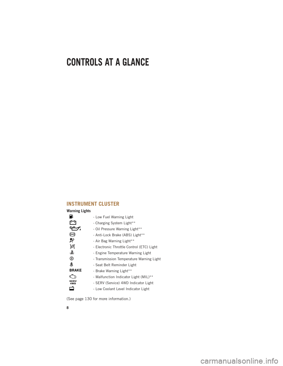
INSTRUMENT CLUSTER
Warning Lights
- Low Fuel Warning Light
- Charging System Light**
- Oil Pressure Warning Light**
- Anti-Lock Brake (ABS) Light**
- Air Bag Warning Light**
- Electronic Throttle Control (ETC) Light
- Engine Temperature Warning Light
- Transmission Temperature Warning Light
- Seat Belt Reminder Light
BRAKE- Brake Warning Light**
- Malfunction Indicator Light (MIL)**
- SERV (Service) 4WD Indicator Light
- Low Coolant Level Indicator Light
(See page 130 for more information.)
CONTROLS AT A GLANCE
8
Page 14 of 196

Engine Starting/Stopping
Starting
• With a valid Keyless Enter-N-Go™ KeyFob inside the vehicle.
• Place the shift lever in PARK or NEU- TRAL.
•
While pressing the brake pedal, press
the ENGINE START/STOP button once.
If the engine fails to start, the starter will
disengage automatically after 10 sec-
onds.
•To stop the cranking of the engine prior
to the engine starting, press the button again.
NOTE:
In case the ignition switch does not change with the push of a button, the RKE
transmitter (Key Fob) may have a low or dead battery. In this situation a back up
method can be used to operate the ignition switch. Put the nose side of the Key Fob
(side opposite of the Emergency Key) against the ENGINE START/STOP button and
push to operate the ignition switch.
Stopping
• Bring the vehicle to a complete stop.
• Place the shift lever in the PARK position.
• Press the ENGINE START/STOP button once. The ignition switch will return to the OFF position.
NOTE:
If the shift lever is not in PARK and the vehicle is in motion, the ENGINE START/STOP button
must be held for two seconds with the vehicle speed above 5 mph (8 km/h) before the
engine will shut off.
GETTING STARTED
12
Page 15 of 196

REMOTE START
• Press the REMOTE START buttonx2on the Key Fob twice within five seconds.
Pressing the REMOTE STARTx2button a third time shuts the engine off.
• To drive the vehicle, press the UNLOCK button, insert the Key Fob in the ignition and turn to the ON/RUN position.
• With remote start, the engine will only run for 15 minutes (timeout) unless the ignition Key Fob is placed in the ON/RUN position.
• The vehicle must be started with the Key Fob after two consecutive timeouts.
WARNING!
• Do not start or run an engine in a closed garage or confined area. Exhaust gas contains Carbon Monoxide (CO) which is odorless and colorless. Carbon
Monoxide is poisonous and can cause you or others to be severely injured or
killed when inhaled.
• Keep Key Fob transmitters away from children. Operation of the Remote Start
System, windows, door locks or other controls could cause you and others to be
severely injured or killed.
THEFT ALARM
To Arm:
• Press the Key Fob LOCK button or the power door lock switch while the door isopen.
To Disarm:
• Press the Key Fob UNLOCK button or turn the ignition to the ON/RUN position.
SEAT BELT
• Be sure everyone in your vehicle is in a seat and using a seat belt properly.
• Position the lap belt across your thighs, below your abdomen. To remove slack in the lap portion, pull up a bit on the shoulder belt. To loosen the lap belt if it is too
tight, tilt the latch plate and pull on the lap belt. A snug belt reduces the risk of
sliding under the belt in a collision.
• Position the shoulder belt on your chest so that it is comfortable and not resting on your neck. The retractor will withdraw any slack in the belt.
•
A shoulder belt placed behind you will not protect you from injury during a collision.
You are more likely to hit your head in a collision if you do not wear your shoulder belt.
The lap and shoulder belt are meant to be used together.
GETTING STARTED
13
Page 27 of 196

ENGINE BREAK-IN RECOMMENDATIONS
• A long break-in period is not required for the engine and drivetrain (transmissionand axle) in your vehicle.
• Drive moderately during the first 300 miles (500 km). After the initial 60 miles (100 km), speeds up to 50 or 55 mph (80 or 90 km/h) are desirable.
• While cruising, brief full-throttle acceleration within the limits of local traffic laws contributes to a good break-in. Wide-open throttle acceleration in low gear can be
detrimental and should be avoided.
• The engine oil installed in the engine at the factory is a high-quality energy conserving type lubricant. Oil changes should be consistent with anticipated
climate conditions under which vehicle operations will occur. For the recom-
mended viscosity and quality grades, refer to “Maintaining Your Vehicle”.
NOTE:
A new engine may consume some oil during its first few thousand miles (kilometers)
of operation. This should be considered a normal part of the break-in and not
interpreted as an indication to an engine problem or malfunction.
CAUTION!
Never use Non-Detergent Oil or Straight Mineral Oil in the engine or damage may
result.
DIESEL ENGINE BREAK-IN RECOMMENDATIONS
For diesel engine break-in recommendations, refer to Diesel Engine Break-In Recom-
mendations on pg.
120
OPERATING YOUR VEHICLE
25
Page 32 of 196

ELECTRONIC RANGE SELECT (ERS) OPERATION
• Electronic Range Select (ERS) allowsyou to limit the highest available trans-
mission gear, and can be activated
during any driving condition. When
towing a trailer or operating the vehicle
in off-road conditions, using ERS shift
control will help you maximize both
performance and engine braking.
• Move the console shift lever left (-) or right (+), or toggle the switch on the
column shift lever down (-) or up (+) to
select the desired top gear.
OPERATING YOUR VEHICLE
30
Page 33 of 196

• For maximum deceleration (engine braking) move the console shift lever left (-)and hold, or toggle the switch on the column shift lever down (-) and hold. Your
vehicle will automatically select the lowest safe gear for optimal engine braking.
• To disable ERS, push and hold the console shift lever to the right (+) or push and hold the column shift lever switch up (+) until “D” is displayed in the odometer.
• Switching between ERS and DRIVE mode can be done at any vehicle speed.
• Refer to your Owner's Manual on the DVD for further details.
ELECTRONIC RANGE SELECT (ERS) OPERATION – 8 SPEED TRANSMISSION
• The Electronic Range Select (ERS) shift control allows the driver to limit
the highest available gear when the
transmission shifter switch is in the
DRIVE position
• You can switch between DRIVE and ERS mode at any vehicle speed.
•
Tapping the ERS (-) switch (on the
steering wheel) will activate ERS mode.
•Once in ERS mode, tapping the ERS (-)
or (+) switch will change the top avail-
able gear.
• To exit ERS mode, simply press and hold the ERS (+) switch until “D” is
once again displayed in the transmis-
sion gear position indicator in the instrument cluster.
OPERATING YOUR VEHICLE
31
Page 35 of 196

NOTE:
Aero Mode may be disabled through vehicle settings in the Electronic Vehicle
Information Center (EVIC) or in the Uconnect
®8.4 Radio (If Equipped).
•
Entry/Exit Mode (Lowers the vehicle approximately 2 in (51 mm)- This position lowers
the vehicle for easier passenger entry and exit as well as lowering the rear of the
vehicle for easier loading and unloading of cargo. To enter Entry/Exit Mode, press
the “Down” button once from the NHR while the vehicle speed is below 33 mph
(53 km/h). Once the vehicle speed goes below 15 mph (24 km/h) the vehicle
height will begin to lower. If the vehicle speed remains between 15 mph (24 km/h)
and 25 mph (40 km/h) for greater than 60 seconds, or the vehicle speed exceeds
25 mph (40 km/h) the Entry/Exit change will be cancelled. To return to Normal
Height Mode, press the “Up” button once while in Entry/Exit or drive the vehicle
over 15 mph (24 km/h). Entry/Exit mode may not be available due to vehicle
payload, an EVIC message will be displayed when this occurs. Refer to "Electronic
Vehicle Information Center (EVIC)" in "Understanding Your Instrument Panel" for
further information.
• Refer to your Owner’s Manual on the DVD for further details.
Air Suspension Modes
• The Air Suspension system has multiple modes to protect the system in unique situations:
Tire Jack Mode
•
To assist with changing a spare tire, the air suspension system has a feature which
allows the automatic leveling to be disabled. Refer to “Electronic Vehicle Information
Center (EVIC)” in “Understanding Your Instrument Panel” for further information.
NOTE:
This mode is intended to be enabled with engine running.
Transport Mode
• To assist with flat bed towing, the air suspension system has a feature which will put the vehicle into Entry/Exit height and disable the automatic load leveling
system. Refer to “Electronic Vehicle Information Center (EVIC)” in “Understand-
ing Your Instrument Panel” for further information.
NOTE:
This mode is intended to be enabled with engine running.
Wheel Alignment Mode
•
Before performing a wheel alignment this mode must be enabled. Refer to “Elec-
tronic Vehicle Information Center (EVIC)” in “Understanding Your Instrument Panel”
for further information.
NOTE:
This mode is intended to be enabled with engine running.
OPERATING YOUR VEHICLE
33